Posts

Convert an AutoCAD profile (a 2D polyline ) into a Civil 3D profile

Image
To convert an AutoCAD profile (a 2D polyline representing a surface profile) into a Civil 3D profile , you need to follow these steps: 1. Understand the Input and Output Input: A 2D polyline representing the profile in AutoCAD. Output: A Civil 3D profile tied to an alignment and a surface. 2. Prerequisites Have an alignment created in Civil 3D. A surface created (optional but recommended). 3. Conversion Steps Step 1: Prepare the Polyline Open your drawing in Civil 3D. Ensure the 2D polyline representing the profile is in the correct location (corresponding to the stationing of the alignment). Step 2: Create an Alignment If an alignment doesn’t already exist: Use the ALIGNMENT creation tools in Civil 3D: Go to Home Tab > Create Design Panel > Alignment > Create Alignment by Layout . Follow the prompts to create an alignment that matches the stationing of your profile. Step 3: Create a Profile View Go to Home Tab > Create Design Panel ...
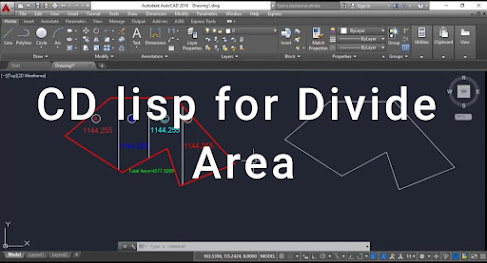
Using CD AutoLISP in AutoCAD to divide an area

Image
  1. Understand the Goal You want to divide a given area into smaller sections (equal or specified). This typically requires identifying boundaries, calculating the divisions, and creating the dividing lines or shapes. 2. Write the LISP Routine Below is an example LISP code to divide a rectangular area into equal parts: (defun c:DivideArea () (prompt "\nSelect a closed polyline to divide: ") (setq obj (car (entsel))) ; Select the closed polyline (setq ent (entget obj)) ; Get entity data (if (= (cdr (assoc 0 ent)) "LWPOLYLINE") ; Check if it's a polyline (progn (setq num-div (getint "\nEnter the number of divisions: ")) ; Get divisions (setq area (vl-cmdf "_.AREA" obj)) ; Calculate area (setq pl (vlax-ename->vla-object obj)) ; Convert to object ;; Get the bounding box (extents) (vla-getboundingbox pl 'minPoint 'maxPoint) (setq minPt (vlax-safearray->list minPoint)) (...

AutoCAD Lisp to Print Multiple Sheets at Once (TPL)

  (TPL) AutoCAD Lisp to Print Multiple Sheets at Once The video titled "(TPL) AutoCAD Lisp to Print Multiple Sheets at Once" demonstrates how to use a custom AutoCAD Lisp routine to efficiently print multiple drawing sheets from model space in a single operation. The routine, referred to as TPL , automates the process of selecting multiple sheet layouts and sending them to a printer or PDF plotter, reducing manual effort and saving time. Key Points from the Video: Selection of Sheets : The routine allows users to specify sheet boundaries or areas within the model space. These areas are predefined for each layout that needs to be printed. Custom Automation : The Lisp script automates the plot command, iterating through the selected layouts and sending them to the designated printer or plotter settings. Users can configure settings like paper size, plot styles, and output formats (e.g., PDF). Eff...

Coordinate Lisp in AutoCAD

Image
  Using a Coordinate Lisp in AutoCAD   A coordinate Lisp routine in AutoCAD is a powerful tool to streamline workflows involving point coordinates. It allows users to automate the extraction, input, or manipulation of coordinates in a drawing, saving time and reducing errors. This article explains the concept, usage, and implementation of a coordinate Lisp in AutoCAD. 1. What is a Coordinate Lisp? A coordinate Lisp routine is a custom script that interacts with points or objects in AutoCAD. It typically handles tasks such as: - Extracting point coordinates from selected objects (e.g., polylines, points, circles). - Inserting points or blocks at specific coordinates. - Exporting coordinates to a file (e.g., CSV, TXT). - Importing coordinates from external files. 2. Benefits of Using Coordinate Lisp Time-saving: Automates repetitive tasks. Accuracy: Reduces manual errors in coordinate handling. Versatility: Handles various coordinate-related workflows, ...

Calculating Areas of Multiple Objects in AutoCAD

Image
Lisp for Calculating Areas of Multiple Objects in AutoCAD ALisp routine can simplify repetitive tasks like calculating the areas of multiple objects (polylines, circles, etc.) in AutoCAD. Below is a guide to creating a Lisp routine that extracts and lists the areas of selected objects. 1. Understanding the Task - AutoCAD objects such asclosed polylines,circles, andregions have an area property. - The Lisp routine will:   1. Allow users to select multiple objects.   2. Extract the area of each selected object.   3. Display or export the calculated areas (e.g., to the command line or a file) 2. Sample Lisp Code   Here is an example Lisp code for calculating the areas of multiple objects:   https://mega.nz/folder/uEwwWYJJ#SqSlsWbhlihseMZO4vL-Fg   lisp (defun c:MultiArea (/ obj area total areas fileName)   ;; Initialize variables   (setq total 0)   (setq areas nil)     ;; Prompt the user to select objects ...

Export station offset & elevation data from civil 3D

Image
Export station offset & elevation data from civil 3D  To export station and offset data from AutoCAD Civil 3D using Harazd 3D Lisp, follow these steps. The article provides an overview of how to set up, utilize, and manage station-offset data export efficiently. 1. Understand Station-Offset Data in Civil 3D Station-offset data in Civil 3D defines the relationship between a baseline (alignment) and other points in the design. Station: The distance along the alignment from a defined start points  Offset: The perpendicular distance from the alignment to the point in question (positive on the right, negative on the left). 2. What is Harazd 3D Lisp? Harazd 3D Lisp is a custom script designed for AutoCAD-based platforms, often used to simplify repetitive Civil 3D tasks such as extracting data points, generating reports, or automating geometry calculations. 3. Setting Up Harazd 3D Lisp Install the Lisp File: Download and place the .lsp file in a directory accessible to Civil 3...

Auto Lisp to Draw Points Boundry in AutoCAD & Civil 3D

Image
Auto Lisp to Draw Points Boundry in   AutoCAD & Civil 3D https://mega.nz/folder/vVRhTKwa#wVslHm6iL2DBKBApKjsUeg